Click to see the list of links
229) A Russian patent of Gnedenko et al.
Ludwik Kowalski (6/10/05)
Department of Mathematical Sciences
Montclair State University, Upper Montclair, NJ, 07043
Today I received a phone call from a reader. That person asked me to translate a Russian patent of Gnedenko and Goriachev. The patent,
according to the caller, is linked with inventions described in units #216 and #226. I said I will do my best and post the translation
at my cold fusion website.
Addendum (6/14/05). The patent description arrived today and I will start translating it. Actually it is a set of four files.
The first is an abstract; it is already in English and I will paste it below. The inventors are listed in alphabetic order; the names
of Koldomasov and Yang (see units #216 and #226) appear of the list. But patent holders are Gnedienko and Goryachev.
FILE #1
Russian Office of Patents and Trademarks
(12) Description of application for patent in the Russian Federation
(21) (22) International Application Number 2002128693/06 October 28, 2002
(24) Priority date October 28, 2002
(46) Publication date July 10, 2004
(56) References: RU 2152083 C1, June 27, 2000, RU 2054604 C1, February 20, 1996, RU 2177512 C1, December 27, 2001, SU 334405 A March 30,
1972, RU 2172526 C2 August 20, 2001.
(98) Address for correspondence:
113149 Moscow, Ul. Sivashskaya 6, Bldg 1, Apt. 191, I. I. Petrov
(72) Inventor: Gnedenko V. G. (RU), Goryachev I. V. (RU), Koldomasov A. I. (RU) Khayunik Yang (KR)
(73) Patent holder:
Gnedenko Valerij Gerasimovich (RU)
Goryachev Igor' Vital'evich (RU)
(54) POWER PLANT FOR PRODUCING HYDROGEN AND OXYGEN
(57) Abstract
An installation designed to produce hydrogen and oxygen, and also for generating power recovered in fusion reactions taking place in
a reactor. The installation includes a dielectric housing that is resistant to a cavitating emission for receiving and transmitting a
dielectric medium in the form of a mixture of light and heavy water, an insert disposed in the housing and made from dielectric
material that is susceptible to cavitating emission and furnished with at least two apertures capable of allowing the dielectric
medium to escape. The installation is furnished with a pulser, a pump for supplying the operating dielectric medium under pressure,
a system for deflecting charged particles, and at least two pipes that are electrically insulated from one another and connected to
receptacles for collecting hydrogen and oxygen, also a stricture in the form of a Laval nozzle at the outlet from the insert in the
housing, and a deflecting system on the housing downstream thereof, after which pipes are arranged. The deflecting system may also
be realized by electrostatic or magnetic means. The invention provides expanded functional capabilities. 2 z.p. files, 1 figure.
(Mixture of light and heavy water)
FILE #2:
This is also an abstract that has already been translated. I am pasting it below. I wish the emphasis was on scientific principles
rather than on the appearance of the device.
FIELD: production of hydrogen and oxygen.
SUBSTANCE: the invention is pertinent to electric power installations. The installation intended for production of hydrogen and oxygen,
and also for production of the energy emitted at fusion reactions going in a reactor. The installation contains: a dielectric resistant
to cavitational emission housing for intake and gating of the dielectric medium in the form of a mixture of light water and heavy water,
an insert mounted in the housing and made out of a dielectric material susceptible to cavitation emission and provided at least with
two holes allowing an exit through them of the dielectric medium. The installation is supplied with a impulsator, a pump to deliver the
working dielectric medium under pressure, a deflecting system of charged particles and, at least, two branch-pipes electrically isolated
from each other and linked with vessels for hydrogen and oxygen collection. At that at exit of the insert in the housing there is a
narrowing in the form of Laval's nozzles, behind it along the stream run on the housing there is a deflecting system mounted, behind
which the branch-pipes are located. The deflecting system may be electrostatic or magnetic. The invention ensures expansion of functionalities
of the installation.
EFFECT: the invention ensures expansion of functionalities of the installation.
3 cl, 1 dwg
FILES #3 AND #4:
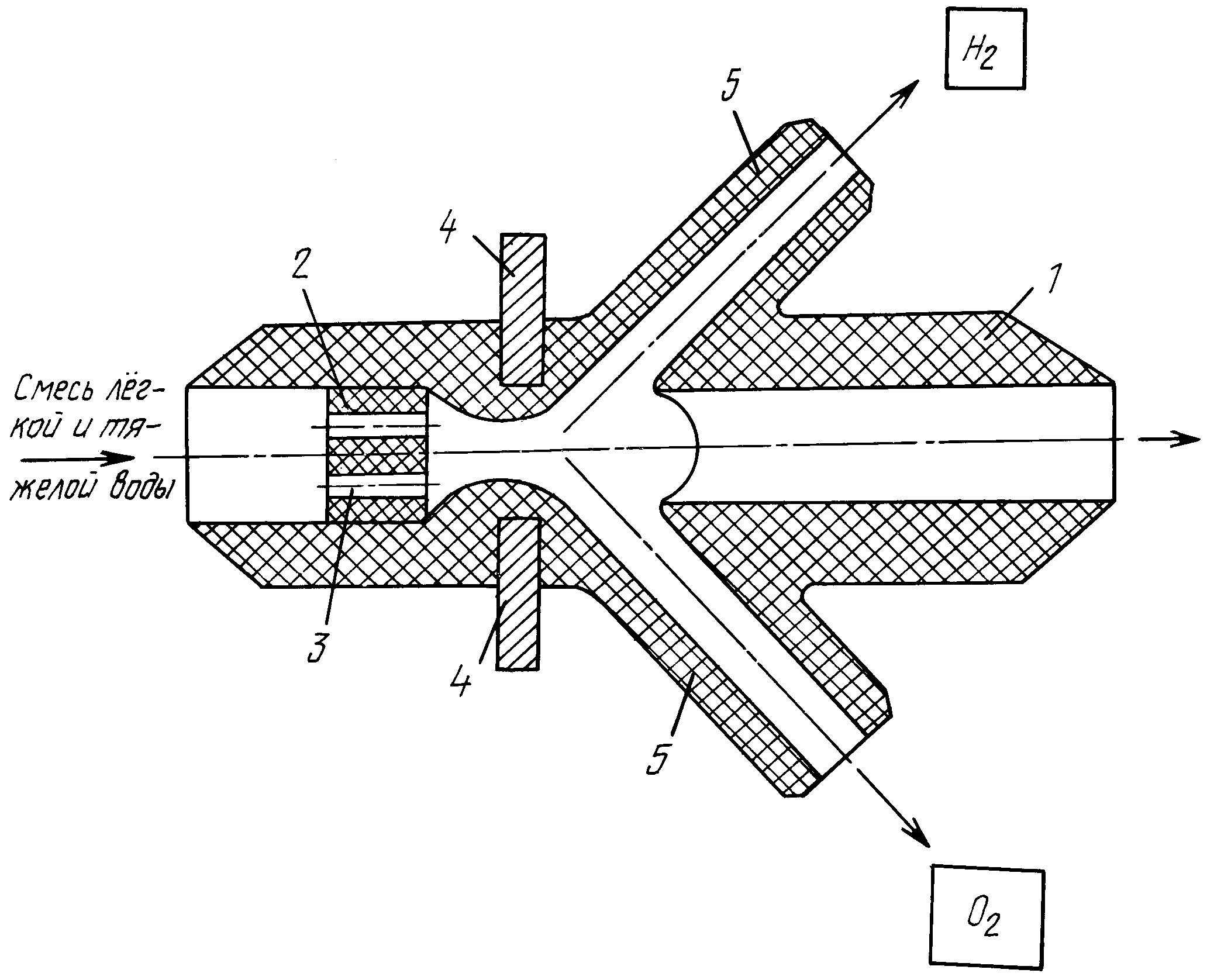
File #4 seems to be an illustration accompanying file #3; that is why I am showing it first. It shows how a “mixture of light and
heavy water” is delivered to the body of the device (from the left input) and how molecular hydrogen and molecular oxygen are removed
(up and down, respectively, as labeled).
File #3 is in Russian. It begins with the abstract (already translated -- see file #1). The abstract is followed by the text shown below.
This text is not clear to me; it makes references to presumably “well known” facts and solutions. Be aware that I am going to translate
without understanding. Most words are clear but I can not make sense of sentences. Some technical terms are new to me and I have no dictionary at
home. For example, what is the “miezelectronnaja camera”? Literally it is a chamber between electrons. But which electrons are they
talking about?
Likewise I am confused by the term “cavitational emission.” I know that cavitation consists of formation of bubble but I do not know
what kind of emission is associated with bubbling. What is being emitted -- particles or waves? If cavitational emission consists of particles
then what is their nature and why are they emitted? If it consists of waves then what kind of waves? Is it sound? Is it Iight? Is it X-rays?
How much energy is emitted? I hope that a reader of this translation will somehow understand it. But I would not be surprised of being accused
of gobbleygooking; that is how the text appears to me, probably due to my limited background in the area of electrical water processing.
Description of the invention:
This invention, based on physics and chemistry, is related to technique of producing hydrogen and oxygen. Being
related to nuclear engineering it can also be used to produce energy liberated in a fusion reactor.
One known solution [a reference to a 1987 Russian book on water purification is given] consists of a tube through which the processed liquid is
delivered to the discharge chamber (with flat and pointed electrodes) and a tube through which it is removed. Also known is a solution [US
patent #3969214, 1976] containing a body with an axial opening, the fluid delivery input located in the lower section, the “miezelectronnaja
camera” [see above], the anode connected to the positive terminal of the power supply, the cathode connected to the negative terminal of
the power supply, and a device producing variable magnetic field.
The limitations of these known inventions is the fact that the anode and the cathode are located on the same side of the “miezelectronnaja
camera” [see above]. Oxygen released at the anode is thus mixed with hydrogen released at the cathode. Mixing of these two gases is accompanied
by endothermic reactions (production of hydrogen peroxide and ozone). These reactions lower the overall efficiency because they absorb part of the
electrolytically generated heat.
Nuclear reactions taking place in the deutron-containing media are well known. They are described by Lipson et al. [two reference to papers published
in 1990 and 1992 -- in the Russian journal “Technical Physics” -- are provided]. Continuos operation is not possible in nuclear reactors
of known type because heat loses increase rapidly with plasma temperature (~T7/2) and energy sources extinguish themselves. Nuclear
reactions are thus not able to supply excess energy needed to overcome coulomb repulsion and sustain nuclear interactions.
The problem can be technically solved [a 1972 reference is mentioned] by inserting one or several dielectric elements into the passage of the liquid.
The pump imposes fluctuations of pressure on the passing dielectric liquid and powerful resonance oscillations at acoustical frequencies (about 1
kHz) are generated in the system. positive electric charges, of high density, appear at the front face of the dielectric insertion through which
the dielectric fluid if passing. The charge density depends on the intensity of cavitation, on the dielectric properties of the insertion and of
the liquid. This leads to generation of quasi-stationary plasma in the liquid, in front of the insertion. The energy content, however, about 1 J/cm,
is not sufficient to compensate for what is used to sustain the plasma discharge.
A known setup, using hydrogen and its isotopes, can generate energy continuously. It consists of a body through which a dielectric medium is flowing.
The body should not be affected by cavitational emission; it should contain a dielectric insertion able to produce cavitational emission. The
insertion should have at least one opening for the passing dielectric fluid, for example light water whose electric resistivity is about
1011 ohm*m. Then approximately 1% of chemically pure heavy water, with identical dielectric parameters, is added. An electrical charge
of high density is then formed in the openings of the insertion. High potential due to that charge is able to ionize hydrogen atoms and accelerate
them sufficiently to overcome coulomb barrier and lead to nuclear reactions. This was described in the 2000 patented prototype (see patent #2152083
of Russian Federation).
The described unit uses only part of the released energy -- excess heat. Our invention removes this limitation of analogous proposals, and of the
prototype. It expands functional possibilities by increasing the intensity of plasma to a level at which energy loses (to sustain plasma) are
compensated, and at which hydrogen and oxygen can be efficiently produced.
The setup produces hydrogen and oxygen. Its body is made from the dielectric material resisting cavitational emission. The insertion is made from
a material able to produce cavitational emission. A dielectric fluid, in the form of a mixture of light and heavy water, passes through at least
two openings in the insertion. The unit is equipped with a pulse generator and with pumps able to supply the compressed dielectric fluid. The setup
is also equipped with a deflection system and with two exit pipes delivering hydrogen and oxygen. The pipes are electrically insulated from each
other. After passing through the insertion the fluid is directed to the Laval’s nuzzle. The deflection system, either electric or magnetic, is
situated after the nuzzle.
The attached figure is a schematic diagram of the energy setup for production of hydrogen and oxygen. Body (1) is made from the dielectric material
that can not be damaged by heat and by cavitational emission. It can be ceramics, sapphire, etc. The insertion (2) is made from a dielectric
material favoring cavitational emission. It can be asbo-cement, ftoroplast, etc. There should be at least one opening (3) in the insertion. Each
opening is a cylindrical channel whose length is 25 to 30 mm and whose diameter is 1 to 2 mm. The deflecting system (4) is mounted in the body of
the device. After the insertion the body has the Laval’s nuzzle and at least two exit pipes (5). The pipes are connected with containers
collecting hydrogen and oxygen. The deflecting system can be either electric, for example, a parallel plate capacitor, or magnetic, for example,
permanent magnets or electromagnets. The magnetic system creates a steady magnetic field in the region between the end of the insertion and the
nuzzle.
The dielectric liquid flowing through the setup pulsates with the frequency that is close to the natural frequency of of the insertion opening.
The resonance amplifies pulsation of the liquid and cavitation takes place at the entrance the of the opening in the insertion. This is associated
with cavitational emission. Exposed to that emission the material from which the insertion is made starts emitting electrons; these electrons enter
the flowing fluid. At the same time positive charge of high density is formed at the entrance of the opening. The difference of potential between
the charged area and earth approaches one million volts. Hydrogen atoms of the working liquid are ionized when they are in the high voltage region.
Positive ions (atomic nuclei of hydrogen isotopes) are then accelerated, inside the liquid, toward the axis of the opening. The concentration of
ions (plasma) increases near the axis. Recombination times are sufficiently long and nuclear reactions can take place.
Impulse that ions receive from positive charges on the wall of the opening can exceed 10 keV. [Why is the term “impulse” used instead
of kinetic energy?] This creates conditions for nuclear fusion reactions. Accelerated nuclei are able to react despite the coulomb barrier. The
rate of nuclear processes can be regulated by changing the concentration of heavy heavy water in light water. The working model has been built;
it works in the following way:
Working fluid is a dielectric -- a mixture of light and heavy water in the ratio of approximately 100:1. It is pumped into the body of the device
(1) under the pressure of 5-7 MPa. The mixture of water flows through the opening (3) in the insertion (2). The insertion is made from a
dielectric material, such as ftoroplast. The length of the opening is 25-30 m; its diameter is 1-2 mm. A pulsator, whose frequency is close to
1 kHz, is used to induce variations of pressure in the flowing mixture. Neither the pump nor the pulsator are shown in the diagram. The resonance
frequency of the opening depends on its length and diameter; it also depends on physical parameters of the fluid. The frequency of the pulsator
is changed slowly to approach the resonance frequency.
The body of the unit can be made from a transparent plastic material. The beginning of nuclear processes can then be recognized because ionizing
radiation emerging from the opening ionizes the surrounding air. It can also be recognized by emission of neutrons, by the increase of temperature
of the working fluid, by chemical changes taking place, and other parameters, using appropriate detectors (neutron counters, thermometers, etc.)
The nuzzle (Laval’s narrowing) is used to speed up working fluid after it becomes ionized. The deflecting system (4) is used to separate
ionized particles. Positive and negative ions are deflected in opposite directions by either electric or magnetic field. By increasing the
concentration of heavy water in light water, for example, to the 100: (3-5) ratio, a change in ionization can be observed. Production of hydrogen
and oxygen increases at the same time. Ionized dielectric fluid moves rapidly through the magnetic field in the nuzzle and ions are subjected to
Lorenz force. That is how positive ions are separated from negative ions. Positive ions move to one exit and negative ions move to another exit.
Relaxation is difficult because the two flows are electrically insulated. In collective vessels Ions recombine and become either hydrogen or
oxygen.
[The last paragraph is the summary of the invention: It is a single sentence consisting of 121 words. It would be very difficult to translate.
I am going to leave this task to a professional translator. In my opinion sentences of that kind are not useful.]
Addendum (6/17/05)
The magnitude of the centripetal Lorentz force is F=q*v*B, where q is the charge of the ion, v is its speed and B is the magnetic field. The
centripetal acceleration due to that force is F/m, where m is the mass of the ion. Comparing this acceleration to v2/R one finds
the formula for the radius of curvature, R=(m*v)/(q*B). The m and q are fixed, for a given kind of ions, but v and B can be adjusted. For
ions of hydrogen ion q=1.6*10-19 C and m=1.67*10-27 kg. Assuming, for example, that v=0.1 m/s (speed of water in the
nuzzle) and that B=0.1 T (due to common magnet) one gets R=10-8 m. That is a very small radius; I do not understand how to make
it consistent with deflection of hydrogen ions in flowing water. Even when v is 10 m/s R is only one micron.
I wish a person familiar with the device could explain cavitational radiation and separation if ions in a flowing water. A student in an
introductory science course would probably asked for the source of energy used to separated atoms of hydrogen from atoms of oxygen in water
molecules. S/he would argue, correctly, that the separation energy, per molecule, must be equal to the energy released when hydrogen is
burned in air (producing water). The authors claim that thermonuclear energy is released in the device. What evidence do they have that
this really happens?
The iESi device is claimed to generate excess heat at the rate of 10 MW. Suppose that this is due to production of helium via cold fusion.
How much helium would be produced in the device each day? It is not difficult to answer this question. The energy released in producing
one helium atom (from two deuterium atoms) is 23.7 MeV. This is 3.8*10-12 J. The excess energy generated at the rate of 10 MW
will produce 10 MJ of energy per second. The number of helium atoms produced in each second must thus be equal
to 10*106/3.8*10-12=2.6*1018. In one day the number of helium atoms would be 24*60*60=86,400 times
larger ( 2.3*1023 atoms). That amounts to easily-detectable 1.5 grams of helium per day. Air, on the other hand, typically
contains no more than several microgram of helium per cubic meter. Reproducible detection of grams of helium, commensurable with excess
energy, would be a highly convincing argument that the excess heat is indeed due to cold fusion of deuterium, as claimed by the inventors.
Addendum (6/19/05)
Browsing the Internet I found the website of PhysOrgForum Science. There I found a recent (6/11/05) posting in which Bearded Clem wrote: “I've been keeping an eye on IESI since I read another cold fusion thread on these boards and recently read on their website that the 2 chief scientists of IESI have come here to Edmonton where I live and I am very interested to find some unbiased proof that what they claim is real because if it is, it will be the breakthrough we need to survive the 21st century. If anyone is interested, here is the text form of a .pdf you can download of the <www.iesiusa.com> website. [See below.] It's a little vague for a skeptic like me but compelling none the less.
White Paper On Plasma Heat and Hydrogen Generator
By Dr. Norman L. Arrison
iESi has acquired the most significant technology of the 21st century through Dr. Hyunik Yang and his team from around the world. Their
technology draws on the energy of the atom and converts that energy into useful energy in the form of heat in one device and the splitting of
the water molecule into hydrogen and oxygen in another device. Dr. Yang's team has varied in size and composition over a ten year period of
research. The consistent aspect of the team has been their international stature and dedication to hard work under the leadership of Dr. Hyunik
Yang. Dr. Hyunik Yang is 47 years of age and has a distinguished record beginning with his B.Sc. in Engineering from Korea followed by his Ph.D.
and post doctorate degrees at Columbia University in New York. He then had a successful career with Hyundai where he was contracted out to NASA
and where he won the Eastman Kodak Award for the best paper and an ASME conference. Dr. Yang then went to Russia where he became a member of the
Russian Academy of Science. With the distinguished scientists Dr. Yang had worked with, they decided to build a unit to produce power for mankind
based on the energy in the atom.
The approach they used was brilliant. They used resonate harmonic frequencies to expose the nuclei of atoms so they could put the nuclei together
to obtain the energy from the fused product. Their system is inexpensive, safe, and easy to operate and construct. The first plasma device will
produce heat by taking water and converting it to steam. This device is expected to be working by late 2004 and an early prototype is already
functioning. the early prototype produces 14 times the energy put into it and the final product is expected to produce 200 times the energy going
into the unit. The second plasma device is expected in early 2005 and it will use it's energy to split the water molecule into hydrogen and oxygen.
This device is already working in an old prototype which produces the hydrogen and oxygen and immediately recombines the two in a hot hydrogen and
oxygen flame. The old hydrogen-oxygen device was the first proof that the team had successfully tapped the energy of the atom. It only produced
50% more energy out than went into the device but showed that the energy of the atom was being drawn upon.
iESi got control of this technology through the special relationship which exists between Dr. Hyunik Yang and Mr. Patrick Cochrane the founder
of iESi. Mr. Patrick Cochrane is married to a Korean attorney and through her got to know of Dr. Yang's work. Mr. Cochrane was so fascinated
with the technology that he helped Dr. Yang with his funding which up to that time had been carried by Dr. Yang and his immediate family. Because
of Mr. Cochrane's assistance for Dr. Yang's work, a close relationship blossomed which has resulted in the formation of iESi as it exists today.
We at iESi feel very proud that we are the ones bringing this historical changing technology to the world. Plasma heat generation alone guarantees
that the cost of electricity will be stable for all mankind. The hydrogen and oxygen producing technology guarantees a clean planet for humanity.
The result is that iESi should be the most significant company of the 21st century.
Quoting a well know cold fusion researcher Clem wrote: “he had reason to believe that a commercial cold fusion device would be marketed
within a year by a group out of Edmonton, Canada.” I am not surprised that a person from that town is so excited about what is going on.
In a 6/14/05 message another contributor (Panthom) wrote: “Since the MIT CF Colloquium, both Professor Peter
Hagelstein and Martin Fleischmann have personally witnessed this cold fusion technology in the facility in Edmonton where IESI has their
scientists sequestered. These two men are providing the unbiased proof the world needs that what they claim at IESI is true. But Patrick
Cochrane at IESI is in legal trouble with the securities authorities in Alberta, so he's being forced out of the company by their investors,
which can only help the company.”
I do not know how reliable this information is. But, as some cold fusion researchers know (from a recent e-mail message sent to them by X),
Martin Fleischmann was invited to participate in the demonstration of the device. The author of that message, X, was also invited. I would
be happy to append a description of the last week Edmonton demonstration.
Click to see the list of links