Click to see the list of links
261) Energy in high voltage electrolysis
Ludwik Kowalski (10/6/05)
Department of Mathematical Sciences
Montclair State University, Upper Montclair, NJ, 07043
Searching for excess heat in Mizuno-type plasma electrolysis
Ludwik Kowalski (a), Scott Little (b), and George Luce (b)
(a) MSU (Montclair State University), Montclair, New Jersey, USA.
(b) ETI (Earth Technology Institute), Austin, Texas, USA.
Excess heat generated in the glow discharge plasma electrolysis, first reported by Mizuno and Ohmori (1), has been studied by several researchers, both in Japan (2, 3, 4) and in other countries (5, 6, 7, 8). Most reports, but not all, confirmed generation of excess heat. Facing this situation we decided to replicate the most recent experiment in which excess heat was found to increase with voltage (8). The planning for the design of this project was described in (9). Considerable progress has been made toward the building and testing of a cell able to operate at high power levels. This work, still in progress, should either confirm or contradict the results reported in (8).
References:
1) Mizuno, T., Ohmori, T., Azumi, K., Akimoto, T., Takahashi, A. “Confirmation of Heat Generation and Anomalous Element Caused by Plasma Electrolysis in the Liquid. in 8th International Conference on Cold Fusion.” 2000. Lerici (La Spezia), Italy: Italian Physical Society, Bologna, Italy. Downloadable from the library at <http://www.lenr-canr.org>
2) T. Mizuno, T.Ohmori, T. Akimoto, and A. Takahashi. “Production of Heat During Plasma Electrolysis.” Jpn. J. Appl. Phys. A, 2000. 39: p. 6055. Downloadable from the library at <http://www.lenr-canr.org
3) T. Mizuno, T. Ohmori and T. Akimoto. “Generation of Heat and Products During Plasma Electrolysis,” in Tenth International Conference on Cold Fusion. 2003. Cambridge, MA. Downloadable from the library at <http://www.lenr-canr.org>
4) T. Mizuno, D. Chang, F. Sesftel and Y. Aoki “Generation of Heat and Products During Plasma Electrolysis,”. in Eleventh International Conference on Condensed Matter Nuclear Science. 2004. Marseille, France. Downloadable from the library at <http://www.lenr-canr.org>
5) Jean-Louis. Naudin et al. Several illustrations and references are downloadable from <http://jlnlabs.imars.com/cfr/index.htm> and from <http://jlnlabs.imars.com/cfr/html/cfrtpwr.htm>
6) Scott R. Little, H. E. Puthoff and Marissa E. Little, “Search for excess heat from Pt electrolyte discharge in K2CO3-H2O and K2CO3-D2O electrolysis.” Downloadable from <http://www.earthtech.org/experiments/lnc-W/Mizuno.html>
7) D. Cirillo, A. Dattilo, V. Iorio, “Transmutation of metal to low energy in confined plasma in the water (electrochemical plasma cell),” ,”. in Eleventh International Conference on Condensed Matter Nuclear Science. 2004. Marseille, France. Downloadable from the library at <http://www.lenr-canr.org>
8) Jean-Francois Fauvarque, Pierre Paul Clauzon and Gerard Jean Michelle Lalleve. “Abnormal excess heat observed during Mizuno-type experiments;” 2005. Downloadable from the library at <http://www.lenr-canr.org>
9) Ludwik Kowalski <http://blake.montclair.edu/~kowalskil/cf/252clauzon.html
WHAT FOLLOWS IS AN ATTEMPT TO DESCRIBE OUR WORK. THIS IS A DRAFT;
IT WILL GROW IN COMING WEEKS. PLEASE REVISIT. PLEASE COMMENT.
kowalskil@mail.montclair.edu
Introduction:
Suppose that a common immersion heater is inserted into a beaker with water. How should thermal energy released in the container depend on the amount of electric energy supplied? The answer is in the law of conservation energy. In a steady state the amount of electric energy, E, supplied during a time interval, t, must be equal to the amount of thermal energy released, Q, during the same interval.
E = Qv + Qc. . . . . . . . . . . . . . (1)
where Qv is thermal energy released by vaporization and Qc is thermal energy released by conduction, convection and radiation. But in the setup described in (8) the sum of the two terms (on the right side of the above equation) was reported to be significantly larger than the electric energy on the left side. The authors believe that some hidden energy, presumably nuclear, is released during the electrolysis. That is the essence of the excess energy claim. To verify it we constructed a similar setup and measured E, Qv and Qc. The work is in progress; the results will be added, probably in three weeks or so. The purpose of this unit is to describe the methodology and to share some observations. The electric energy on the left side is the integral of dE = i(t)*v(t)*dt, over a test duration.
E = integral(dE) . . . . . . . . . . (2)
where i(t) and v(t) are the instantaneous current and voltage between the electrodes, respectively. Instruments used to measure E are described in the appendix. To measure Qv one must determine the amount of water evaporated, Mp, during the plasma test
Qv = Mp*L . . . . . . . . . . . . . . (3)
(4) where L is the latent heat of evaporation. Two measurements of the evaporated mass were performed, one when the current was flowing through the electrolyte, giving us Mp, and another, when the current was flowing through the ohmic heater immersed in the electrolyte, giving us Mo. The value of Qc can be calculated as
Qc = L*(Mt-Mo) . . . . . . . . . (4)
where L*Mt is the amount of thermal energy that would be lost if evaporation were the only way of loosing heat. In
other words Mt*L is nothing else but electric energy, Eo, measured at the same time as
Mo. In other words, Qc = Eo - L*M
o and excess heat, H, is given by:
H = Qv + Qc - Eo = L*(Mp -
Mo)+ (Ep - Eo) . . . . . . . . (5)
Note that excess heat becimes L*(Mp-Mo) when Ep and
Eo are identical. This relation is intuitively obvious without the derivation. Nuances involved in experimental determinations
of H will be addressed in the next section. The equation (1) is certainly satisfied when an ohmic resistor is used to sustain boiling. But will it
also be satisfied when boiling takes place during the high voltage electrolysis? That is the question we want to answer.
Experimental setup
According to the sketch, shown in unit #252, the setup is conceptually simple. But gathering reproducible data turned out to be difficult. Two differences between the initial sketch and the actually used setup had to be made to match (8) as close as possible. Instead of a spiral Pt anode we used a cylinder made from the platinized titanium mesh. The height of that cylinder was 5 cm and its diameter was 6.3 cm. The anode was a welding tungsten rod containing 2% of thorium. The electrolyte, as in (8), was a 0.2 M solution of K2CO3 in distilled water. To keep the volume of the boiling electrolyte constant the evaporated water was continuously replaced by fresh water coming from an auxiliary reservoir. As shown in Figure 1, that reservoir was mounted on the same support as the scale.
The temperature of water in the reservoir, T, typically 25 C, was constantly monitored. If that temperature were 100 C then the value of L, to be used in formulas (3) and (4), would be 2260 J/g. At a lower T, however, the effective latent heat of evaporation is 2260+4.186*(100-T). Thus the effective L is 2594 J/g at 20 C and 2553 at 30 C. Two thermistors were used, one to monitor the temperature of the electrolyte and another to measure T of water. A simple open beaker, turned out to unsuitable above 250 volts, due to splashing of the electrolyte. The beaker was thus replaced by a taller cylindrical vessel made from polycarbonate. The depth and the inner diameter of that vessel were 32.0 cm and 11 cm, respectively. A set of ani-splashing baffles was mounted near the top of the vessel, as illustrated below.
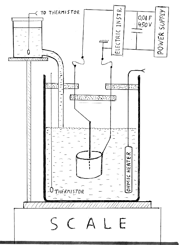
FIGURE 1
Schematic diagram of our first setup. The volume of the electrolyte was 650 cubic centimeters. The dotted baffles, in the upper section of the cell, offer an
escape path to the vapor but not to the splashing electrolyte. Vertical rods supporting the electrodes are mounted on these baffles. The “electrical
instruments” box, at the upper right corner, stands for the Clark-Hess meter (model 3200). It is essentially a set of three digital instruments: an
ammeter, a voltmeter and a wattmeter.
= = = = = = = = = = = = = = = = = = = = = = = = = = = = = = =
Masses of water evaporated in consecutive tests (Mp and Mo were determined from the readings of the scale. Light
flexible filaments were used to connect electrical components inside the vessel with outside circuits. That arrangement did not prevent us from measuring
mass differences (typically 40 grams) with a sufficient accuracy (at least 0.5%). The entire vessel was wrapped in a layer of polyethylene foam. The
purpose of that thermal isolation was to keep the walls temperature as high as possible in order to minimize condensation of vapors on the inner surface.
Condensed water dripping back into the electrolyte would reduce values of m1 and Mo . Splashing, on the
other hand, would make Mp and Mo larger than what were evaporated.
Note that the intensity of splashing, if not mechanically reduced, would increase with the applied voltage. This could possibly create an illusion of a
voltage-dependent excess heat. The same kind of illusion could occur if the “invisible splashing” was significant. Ideally only water vapor (plus
some hydrogen and oxygen) should escape from the electrolyte. Suspecting that tiny droplets of electrolyte might also be escaping from the cell we compared
concentrations of the electrolyte before and after some tests. These two concentrations should be the same because evaporated water is replaced by fresh
water. But replacing droplets of the electrolyte with water would make the second concentration smaller than the first. A reduction of the concentration
was noticeable but not significant to create an illusion of excess heat. Another possibility of a systematic error, could possibly occur if the rising
temperature of water in the reservoir were not taken under consideration. The flow of steam escaping from the vessel increases with voltage and affects
the temperature in the reservoir. This, in turn, changes the value of L used in formulas 3 and 4. Using L=2595 (correct at 20 C) when in reality it is
2427 (at 40 C), for example, would create an illusion that Qv and Qc are 7% higher.
The ohmic heater was used to preheat the electrolyte to the boiling temperature and to measure Mo. After that the ohmic
heater was turned off and boiling was maintained by the current flowing through the electrolyte. The evaporated masses m1 were measured after the ohmic
heater was turned off and after desired voltages were applied between the anode and the cathode. The Figure 2 shows time dependencies of our two most
essential parameters. The line labeled “masses” refers to evaporated water (Mp or Mo
in grams along the left-vertical axis). Likewise, the line labeled “energies” refers integrated electric energy (E in kJ along the right-vertical
axis). Other measured, or computer-calculated, parameters were also monitored during the experiments but their time dependencies are not shown in the
figure below. The mass lost was essentially zero until the boiling temperature was reached. After that the amount of water evaporated started increasing.
The segment AB of the mass curve was used to determine Mo. The segments CD and EF of that curve were used to determine
Mp at two different voltages. The corresponding segments of the energy curve, A'B', C'D' and E'F' were used to determine
the values of the energy received in the matching time intervals.
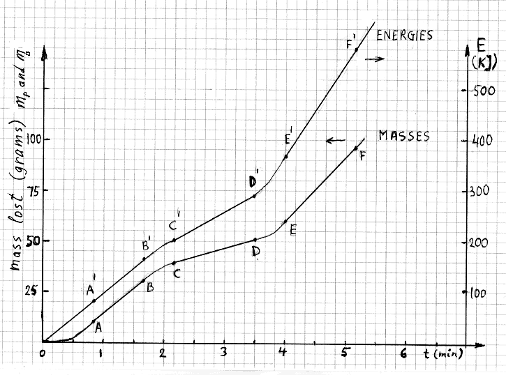
FIGURE 2
Typical time dependencies of Mp (or Mo) and of E for three short tests. Boiling point was
reached at t=0.5 min but the first test started (in this hypothetical illustration) at t=0.833 min.
= = = = = = = = = = = = = = = = = = = = = = = = = = = = = = =
Due to micro explosions in the electrolyte, especially in tests above 300 volts, the mass curves often displayed wiggles (not shown in figure 2). Wiggles,
representing dynamic effects on the scale, did not interfere with determinations of masses of the evaporated water because only initial and final readings
were needed. We were always able to stop cell shaking by lowering the voltage for three to five seconds.
Results
Figure 3 shows how the rates of non evaporative losses (measured with the ohmic heater) depended on the electric power. The values of electric power,
in watts, are shown along the horizontal axis while the vertical axis shows rates of non evaporative losses (also in watts). The rate of loosing heat by
conduction and convection increases with electric power. This is an expected result; the rising column of steam acts as an air pump which drives convection
currents more strongly than when generation of steam is less intense. Furthermore, more rapid boiling is equivalent to more intensive mixing of the
electrolyte. This too is likely to increase the rate of cooling by conduction and convection.
The values of E, Qv and Qo, at different voltages, are shown in the table below. Most cells
of this table contains two numbers; the mean value and the standard deviation. For example, a cell at the intersection of the row labeled 300 V and the
column labeled E, shows that the . . .
Single numbers, in the last column, labeled COP, are coefficient of productivity at different voltages. By definition:
COP = (Qv + Qc) / E
The numerical values of COP were calculated from the mean values of Qv, Qc and E, at corresponding voltages. The
data show that . . .
Please revisit this unit in November to see the results.
APPENDIX 1
Measuring electric energy
The electric energy E, delivered to a cell, is the integral (over a test duration) of dE = i(t)*v(t)*dt. The instrument we used, Clark-Hess model 2330 power
analyzer, sampled the v(t) and i(t) about 2000 times per second. As expected, the voltage between the cell electrodes, v(t), was essentially constant but
the current i(t) was highly irregular. Digitized samples of v(t) and i(t) were recorded by the computer and the cumulative E was displayed during the data
acquisition, as shown in Figure 2. A highly irregular nature of the i(t) waveform guarantees random sampling and the average energy, over a time longer
than several seconds, is highly reliable. To verify this we also used an a.c. watt meter at the input of our d.c. power supply. The a.c. energy, E',
measured with that instrument was only slightly larger than the d.c. energy, E. The difference, (E'-E), was consistent with what is necessary to operate
the power supply when it is not loaded. A high quality digital multimeter, Fluke 87, was also used to measure the mean current. The result was identical
with the mean current measured by the Clark-Hess instrument.
APPENDIX 2
Measuring electric energy
A polycarbonate cell whose height and internal diameter were . . . cm and .... cm, respectively, replaced the taller cell used in the previous set of
experiments. The new cell (see Figure 4) has a lid made from the linen-based phenolic plastic. The lid is firmly attached to the cell with four
nylon-tipped screws. The electrodes, the water reservoir, the ohmic heater, and the thermistor are now mounted on the lid. A PVC exhaust pipe, whose
inner diameter is 2.54 cm, is also mounted on the lid. Its purpose is to conduct steam escaping into air. A plastic baffle, placed 2 cm below the pipe’s
input (inside the cell), is an effective shield against consequences of splashing the electrolyte.
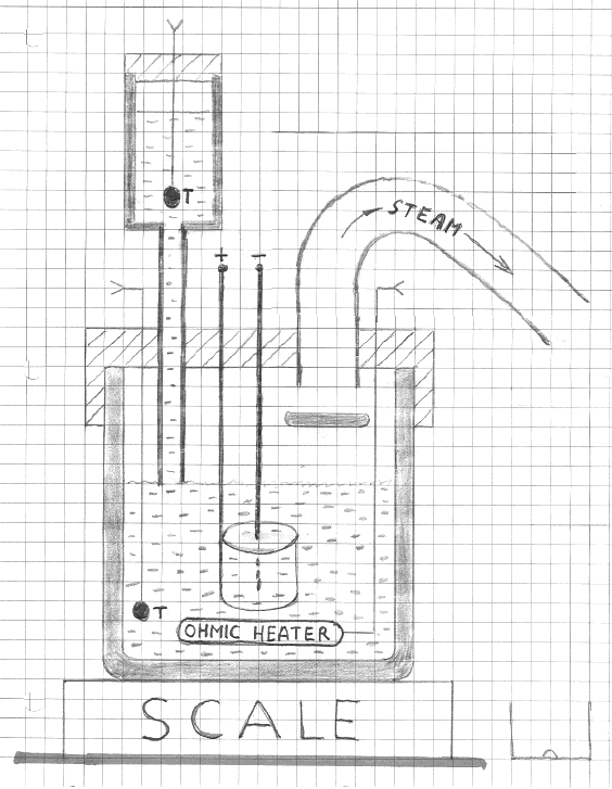
FIGURE 4
Schematic diagram of our second setup.
Some condensation is expected to occur on the inner surface of the exhaust pipe, mostly in the outermost section where the temperature is the lowest.
That section was directed downward so that drops of water could drip down to be collected. Note that in a vertical pipe condensed water would return to
the electrolyte. Also note that steam ejected from the cell is kept away from the water reservoir and from electrical connections above the lid.
The Pt-coated Ti mesh anode, same as before,is now supported by two titanium rods (instead of one) to minimize shaking. As before, the exposed end of
the tungsten cathode (about 1 cm) was located at the center of the cylindrical anode. One of the problems encountered with the previously used cell
was arcing between the electrodes in the space above the electrolyte. All metallic components in the new cell are covered with insulation. Hopefully
this will reduce the probability of arcing.
NOT TO FORGET:
1) Recognizing that the idea of measuring the concentration of salt in the electrolyte (before versus after a test, in order to investigate a possibility
of ejection of tiny droplets) was suggested to us by Dennis Cravens. Also his critical comments on measuring E.
2) Electroplating as a method of calibrating our C-H ammeter, if necessary.
3) Recognizing Clauzon's help in providing details about their setup.
4) Try to understand presence of tungsten in the water reservoir (discovered with the X-ray fluorescence instrument)
5) Recognizing Puthoff's (ETI?) hospitality, contribution and encouragements.
6) ?
Click to see the list of links