Click to see the list of links
337) On emission of nuclear radiation due to glow discharge
Ludwik Kowalski; 11/17/2007
Department of Mathematical Sciences
Montclair State University, Montclair, NJ, USA
In 2002 my renewed interest in cold fusion was triggered by research of Karabut (unit #13 at my website). That was five years ago. I was impressed by the description
of spectacular nuclear effects due to the glow discharge. During a workshop in Italy (Catania, October 2007) I was equally impressed by the ongoing research of Ed Storms
and Brian Scanlan. Their glow discharge apparatus is also said to produce nuclear effect -- emission of high energy electrons (0.8 MeV) and of yet to be identified heavier
projectiles, perhaps protons, neutrons or alpha particles. This unit is devoted to what I learned about this recently-started investigation, and to my understanding
of it. The report of S & S can be downloaded from the LENR-CANR library (1).
The glow discharge apparatus is essentially a diode filled with a gas at low pressure. The gas starts glowing when sufficiently high voltage is applied. The distance
between the anode and the cathode, in the S&S setup, was about 8 mm. Their gas was D2, mixed with small amounts of oxyge. The pressure was probably close to 10 Torr.
Essential components of the apparatus are identified in Figure 1. The figure is not geometrically realistic; it was made to match my simplified description.
= = = = = = = =
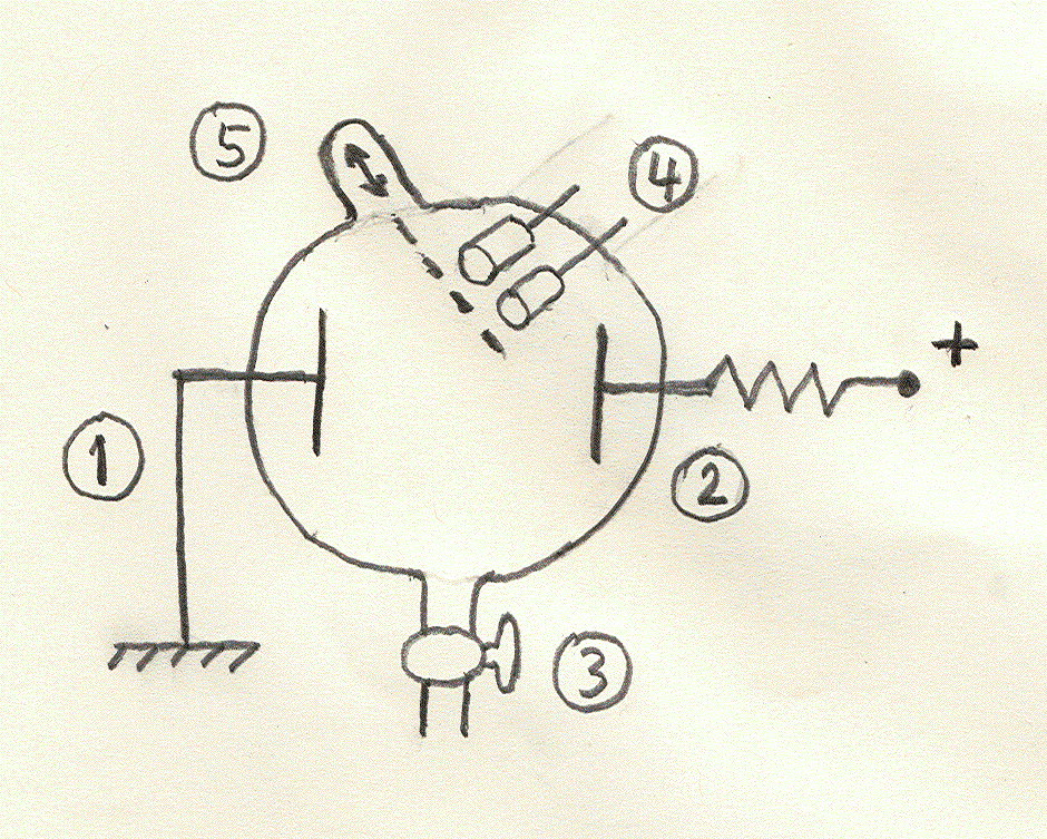
Figure 1
A schematic diagram of the apparatus used by Storms and Scanlan.
1 Grounded water-cooled cathode
2 Anode connected to the power supply via a 300 ohms resistor.
3 Valve leading to the vacuum and gas supply tubes.
4 Two detectors of nuclear radiation (GM and SBD) facing the cathode.
5 A filter of desired thickness can be inserted, as needed.
= = = = = = = = = = = = = = = = = = = = = = = = = = =
According to preliminary investigation, based on the Geiger Muller counter (with and without filters), nuclear radiation is emitted when appropriate voltage is applied
to sustain the glow discharge. My first reaction to this claim, after hearing Storms’ presentation in Catania, was that the GM detector is probably
picking up radio waves generated during the discharge. Three reasonable arguments were presented against this suspicion:
a) Placing a thin filter, of sufficient thickness (either metal or dielectric), between the cathode and the detector, reduces the counting rate to the background level.
b) The effect increases at a rate that is proportional to the D/O ratio.
c) The effect tends to disappear when hydrocarbons are added.
2) In a brief discussion I suggested an additional test, to rule out the possibility that high counting rates (exceeding million counts per second) are due to the radio-waves
artifact. It consists of studying the effect of the voltage, applied to the GM tube, on the counting rate.
a) Use any radioactive source to establish the minimum voltage below which counting becomes impossible. Suppose the GM plateau region is between 700 and 900 volts and that
nothing is counted below 550 volts.
b) Conduct an experiment at 800 volts to observe the claimed effect.
c) Lower the GM voltage to to 500 volts and repeat the experiment.
My level of confidence in the claimed effect would increase dramatically if the high counting rate remained essentially constant in the plateau region and dropped to zero
at 500 volts. The radio waves idea (or propagation of disturbabces along wires), on the other hand, would be confirmed if the GM was still counting at 500 volts. Rick Cantwell,
who conducts glow discharge investigations in Colorado, also made a presentation in Catania. My understanding was that he will try to confirm the S&S results. I hope that
he and the S&S team will soon conduct the suggested test and post the results on the private Internet list for CMNS researchers. On my agenda that would be the test #1.
Nothing would be investigated with a GM detector responding to electromagnetic disturbances associated with the discharge.
3) According to S&S report, two kinds of radiation are emitted: monoenergetic electrons (0.8 MeV) and heavier particles. Heavier particles have not yet been identified.
Electrons are said to be emitted at the rate of billions per second. How was energy of electrons determined with a GM counter? By the use of filters, as illustrated in
Figure 2. In the original report (1) this was Figure 9.
= = = = = = = =
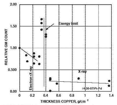
Figure 2
Counting rate verus the copper filter thickness.
= = = = = = = = = = = = = = = = = = = = = = = = = = =
It shows that the counting range drops suddenly when the total thickness of filters becomes 400 mg/cm2. That corresponds to monoenergetic electrons of 0.8
MeV. If the drop occurred at 500 mg/cm2 then the energy attributed to electrons would 1.0 MeV, etc., according to a ranfe-energy formula for electrons. But
the figure also shows a peak, at the thickness of about 350 mg/cm2. The report states that the peak is due to bremsstrahlung radiation. Unfortunately,
this is not at all convincing. My expectation would be a monotonic increase of the intensity of BR up to the maximum thickness of 400 mg/cm2. The combined
intensity (electrons plus BR) should not produce a very narrow peak at 350 mg/cm2. I suspect that some kind of artifact is responsible for
the shape of the curve in Figure 2. What can it be? To answer to this question I would like to know what absolute counting rates were. The numbers along the
vertical axis are relative counts, where 1.0 is assigned to the result without a filter. The absolute values were probably close to 100. How else could wide
fluctuations of data points (with respect to straight segments) be explained?
4) Referring to results obtained with the SBD (surface barrier detector), the report states that “charged particles having several energies were detected.”
Unfortunately, the spectrum with energy peaks is not shown. Monoenergrtic electrons of 0.8 MeV would produce their own peak in that spectrum. I will insert
additional information when it becomes available, probably in another formal progress report or via our private Internet discussion list. This is an interesting
line of research; I will try to follow its future developments.
Footnote:
I am composing this unit after receiving a message from a stranger. That person asked me why was nothing new posted at my CF website for many months.
Appended on 11/19/07:
= = = = = = = = = = = =
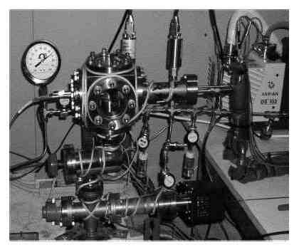
Figure 3
The overall view of the S&S apparatus.
= = = = = = = = = = = = = = = = = = = = = = = = = = =
The overall view of the apparatus in Figure 3 shows its complexity, as far as practical implementation of a simple idea is concerned. The anode (see Fig 1) was made from
Pd wire of 2 mm diameter. Cathodes, in the form of removable foils, were made from several materials, such as copper, palladium and silver. The observed results were
more or less the same when different cathodes were used.
References:
1) Go to http://www/lenr-canr.org and click on “library.” Files are listed alphabetically (accordig to the first author). Scroll to a file you want and
click the “download.”
Click to see the list of links